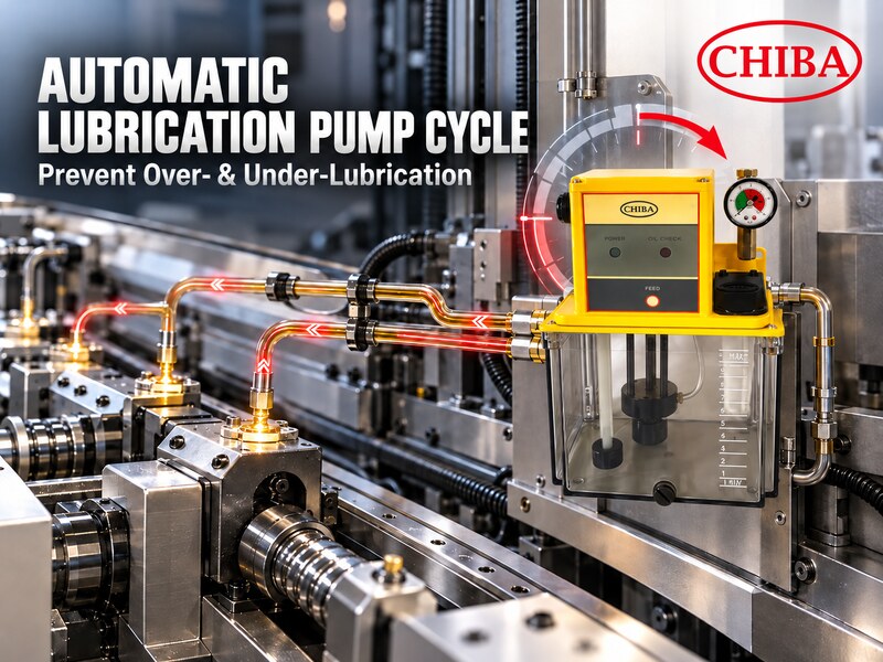
How to Set an Automatic Lubrication Pump Cycle for Industrial Machinery
How to Set an Automatic Lubrication Pump Cycle for Industrial Machinery
How to prevent over-lubrication and under-lubrication by evaluating lubricant demand, pump output, metering components, piping, controls, and actual machine conditions.
An automatic lubrication pump cycle defines when the pump starts, how long it runs, and how often lubricant is delivered to industrial machinery. A properly configured cycle helps maintain lubrication at bearings, linear guides, gears, sliding surfaces, and other friction points without supplying more oil than the machine requires.
At YUNG TIEN LUBRICATION TECHNOLOGY CO., LTD., we manufacture CHIBA lubrication pumps, distributors, tubing, and related components for industrial machinery. When evaluating a lubrication cycle, we consider the pump together with the lubricant, metering components, piping arrangement, control method, and actual operating conditions. Timer settings alone cannot confirm that every lubrication point receives the intended amount.
This guide explains how to establish an initial lubrication cycle, estimate lubricant requirements, diagnose incorrect settings, and evaluate a suitable CHIBA lubricator and control method.
Quick Answer An automatic lubrication pump cycle should be set according to the required lubricant quantity at each point, pump output, metering components, piping conditions, lubricant viscosity, machine runtime, and control method. Reservoir size or timer settings alone cannot determine whether the machine receives the correct amount of lubricant.
Table of Contents
- What Is an Automatic Lubrication Pump Cycle?
- What Information Is Needed Before Setting the Lubrication Cycle?
- How Do You Estimate the Required Lubricant Quantity?
- How Do Pump Output, Metering Components, and Piping Affect the Cycle?
- How Can You Identify and Correct an Incorrect Lubrication Cycle?
- How Do You Match a CHIBA Lubricator with the Required Control Method?
- Frequently Asked Questions About Automatic Lubrication Pump Cycles
1. What Is an Automatic Lubrication Pump Cycle?
An automatic lubrication pump cycle is the operating sequence used to supply lubricant at predetermined intervals. Depending on the pump and control configuration, it may include:
- Pump running time
- Off time or interval time
- Quantity delivered during each operation
- Number of lubrication cycles per shift or day
- Internally timed or PLC-controlled activation
For example, a lubricator may operate for a defined period and then remain off until the next scheduled cycle. In another configuration, the machine PLC may activate the auto pump according to production cycles or machine operating status.
A shorter interval is not necessarily a better setting. Lubrication should be frequent enough to maintain the required lubricant film, but not so frequent that it causes excessive oil accumulation, leakage, contamination, or unnecessary consumption.
Reservoir capacity should not be confused with lubricant output. Reservoir capacity indicates how much lubricant the unit can store, while pump output, running time, and distribution components influence how much lubricant enters and moves through the system.
2. What Information Is Needed Before Setting the Lubrication Cycle?
Before setting the lubrication pump timer, we recommend collecting information about the lubrication points, machine operation, lubricant, pump, and distribution arrangement.
Lubrication-Point Requirements
- Number and location of lubrication points
- Type and size of each lubricated component
- Required lubricant quantity at each point
- Required lubrication frequency
- Whether different points have different requirements
- Accessibility and installation restrictions
A bearing, linear guide, gear set, and sliding surface may require different quantities and replenishment intervals. Therefore, the total number of points alone is not enough to establish a reliable cycle.
Machine Operating Conditions
- Daily operating hours
- Machine speed and load
- Start-and-stop frequency
- Production cycle
- Ambient and operating temperatures
- Dust, moisture, and other contaminants
- Differences between production shifts
Two machines using the same lubricator may still require different settings if their operating hours, loads, speeds, or environmental conditions differ.
Lubricant and System Conditions
- Lubricant type and viscosity
- Pump output and pressure range
- Distributor or metering-component specifications
- Pipe diameter and total length
- Number of branches, bends, and fittings
- Control voltage
- Internal timer or PLC requirements
- Oil-level or pressure-monitoring requirements
Whenever available, follow the machinery or component manufacturer’s lubrication recommendations. These instructions should provide the starting point for lubricant type, quantity, and frequency.
Key Takeaways
- Do not determine the cycle from the pump model alone.
- Different lubrication points may require different quantities.
- Runtime, speed, load, and temperature can change lubrication demand.
- The lubricant, pump, distributor, and piping must be evaluated together.
3. How Do You Estimate the Required Lubricant Quantity?
The required lubricant quantity should be established before it is converted into pump running time and interval settings.
Required lubricant per cycle = the sum of the required quantities for all lubrication points
If the machine requires several lubrication cycles per day:
Estimated daily lubricant demand = lubricant required per cycle × number of cycles per day
This is a conceptual estimate rather than a universal engineering formula. The required quantity for each point should first be obtained from the machine or component manufacturer, an established lubrication calculation, or qualified application data.
Practical Estimation Process
- List every lubrication point.
- Identify the required quantity for each point.
- Add the individual quantities to calculate total demand per cycle.
- Determine the required replenishment frequency.
- Compare the requirement with the pump output and metering-component capacity.
- Establish an initial running time and interval.
- Verify delivery using an appropriate and safe inspection method.
- Adjust the setting based on documented operating results.
If different lubrication points require different quantities, calculate each point separately before adding the values together. Multiplying one assumed quantity by the total number of points may produce an inaccurate result.
The objective is not to maximize lubricant delivery. It is to supply the appropriate amount at a suitable interval.
4. How Do Pump Output, Metering Components, and Piping Affect the Cycle?
A lubrication pump timer controls when the pump operates, but it does not independently determine how much oil reaches each lubrication point.
Actual system performance depends on:
- Pump output and available pressure
- Metering or distribution components
- Lubricant viscosity
- Pipe diameter and length
- Fittings, bends, and branches
- Backpressure at the lubrication points
- Operating temperature
- Control sequence
Pump Output and Running Time
A simplified nominal relationship is:
Nominal pump output per operation = rated output × running time
The result should not automatically be treated as the confirmed quantity delivered to every lubrication point. System resistance, metering components, piping, and lubricant condition can affect delivery time, operating pressure, and whether the intended quantity successfully reaches each point.
Quantitative Lubrication and Metering Components
The phrase quantitative lubrication pump is commonly used as a search term. In practice, precise delivery at each point generally depends on the complete metering and distribution arrangement rather than the pump alone.
A quantitative lubrication system may include:
- A compatible lubrication pump
- Metering or distribution components
- Properly sized piping and fittings
- Correctly configured lubrication points
- A suitable operating and control sequence
The pump supplies lubricant to the circuit, while the selected metering or distribution components help determine how the lubricant is allocated.
Piping Resistance
Long pipe runs, small internal diameters, numerous fittings, high lubricant viscosity, low temperatures, contamination, and high downstream resistance can delay lubricant delivery or increase system pressure.
Increasing the running time without inspecting the piping may conceal the original problem. It may also cause properly functioning points to receive excessive oil while a restricted point remains insufficiently lubricated.
Key Takeaways
- Timer settings do not independently control delivery at each point.
- Pump output must be matched with the distribution arrangement.
- Piping conditions can affect pressure and delivery time.
- Evaluate the complete system instead of selecting components separately.
Related Reading:
- Resistance vs. Pressure-Relief: Selecting the Right Quantitative Lubrication Pump for Your System
- How to Choose a Pressure-Relief Lubrication Pump: 5 Key Factors Every Manufacturer Should Consider
5. How Can You Identify and Correct an Incorrect Lubrication Cycle?
An unsuitable cycle may result in over-lubrication, under-lubrication, delayed delivery, or uneven distribution. However, these conditions are not always caused by the timer.
| Condition | Possible Causes | Observable Signs |
|---|---|---|
| Over-lubrication | Interval too short, running time too long, or excessive quantity per cycle | Oil accumulation, leakage, contamination, or unusually high consumption |
| Under-lubrication | Interval too long, inadequate delivery, or low oil level | Increased noise, temperature, friction, or component wear |
| Uneven delivery | Piping differences, leakage, blockage, or unsuitable distribution components | Some points receive oil while others remain insufficiently lubricated |
| Delayed delivery | High viscosity, low temperature, long piping, or air in the system | Oil does not reach the intended point within the expected time |
| Abnormal consumption | Leakage, changed settings, or component problems | Reservoir level falls faster than expected |
These signs are diagnostic indicators rather than proof of a single cause. A dry lubrication point does not necessarily mean the interval is too long. The cause may be a blocked line, leaking fitting, trapped air, unsuitable metering component, or insufficient operating pressure.
Recommended Inspection and Adjustment Procedure
- Confirm that the correct lubricant is being used.
- Check the lubricant level.
- Inspect accessible piping and fittings for leakage or damage.
- Check for trapped air, contamination, or blockage.
- Confirm that metering or distribution components operate as intended.
- Verify delivery using a safe inspection method appropriate for the machine.
- Change only one timer parameter at a time.
- Record the original setting and every adjustment.
- Observe the machine through a suitable operating period.
Safe verification may include checking accessible outlets during commissioning, reviewing distributor operation, or using available pressure and monitoring signals. Inspection must follow the machine manufacturer’s safety procedures.
External safety references: ISO 12100 — Safety of Machinery and OSHA Control of Hazardous Energy Guidance .
Key Takeaways
- Inspect the complete circuit before changing timer settings.
- Pump operation does not prove that every point receives lubricant.
- Change one parameter at a time and document the results.
- Use inspection methods appropriate for the machine and environment.
Related Reading:
- How to Maintain an Auto Oil Lubrication Pump? Common Issues and Tips
- Lubrication Pump Replacement Guide: What to Check Before Replacing an Obsolete or Failed Unit
6. How Do You Match a CHIBA Lubricator with the Required Control Method?
Our resistance-type oil lubrication range includes the SMA, TM, MFE, and TM-2 series. These products provide different output, pressure, voltage, timing, and monitoring configurations. The final model should therefore be evaluated against the complete application rather than selected by appearance or reservoir capacity alone.
SMA Intermittent Lubrication Pump
The SMA series uses a motor-driven, gear-operated piston mechanism for intermittent oil delivery. Published specifications provide several predefined off-time options, while a float switch is available as an option. Output and pressure vary by model.
TM Engine Oil Resistant Lubrication Pump
The TM series is listed in our resistance-type oil lubrication category and includes PLC-controlled and internally timed configurations. Published configurations also include oil-level detection and pressure-setting features.
MFE Pump with LCD Display
The MFE series includes PLC-controlled and internally timed configurations. Published features include oil-level detection, adjustable pressure output, an instant-operation control, and applicable pressure-detection functions.
TM-2 Engine Oil Resistant Lubrication Pump
The TM-2 series is presented with PLC or pump-based timing control, oil-level detection, oil-delivery, and pressure-setting functions. Compatibility must be checked against the complete lubrication circuit.
Selecting the Appropriate Configuration
When comparing CHIBA lubricators, confirm:
- Required output and pressure
- Internally timed or PLC-controlled operation
- Required oil-level or pressure monitoring
- Voltage
- Reservoir requirements
- Distributor and piping compatibility
- Installation conditions
A higher nominal output or larger reservoir is not automatically better. The correct configuration is the one that works with the lubricant, control sequence, metering components, piping, and machine requirements.
Key Takeaways
- Select a lubricator according to the complete lubrication circuit.
- Confirm whether independent timing or PLC integration is required.
- Match pump output with the metering and distribution components.
- Verify the exact specifications of the selected model.
Related Reading:
- How to Choose an Auto Oil Lubrication Pump
- What Is an Auto Oil Lubrication Pump?
- Does Your Equipment Need Automatic Lubrication?
7. Frequently Asked Questions About Automatic Lubrication Pump Cycles
How often should an automatic lubrication pump operate?
There is no universal interval for every machine. Lubrication frequency depends on the requirements of each lubrication point, pump output, distribution components, machine runtime, load, speed, temperature, lubricant, and operating environment.
Start with the machine or component manufacturer’s recommendation when available, and verify the setting under actual operating conditions.
Can the lubrication cycle be determined by reservoir capacity alone?
No. Reservoir capacity mainly affects lubricant storage and refill frequency. It does not represent the quantity delivered during each cycle.
The delivered quantity depends on pump output, running time, metering components, distribution method, and system conditions.
Why is the auto pump operating but some points receive no oil?
Possible causes include:
- Low oil level
- Trapped air
- Leaking fittings
- Blocked or damaged piping
- Contaminated lubricant
- Unsuitable or malfunctioning distribution components
- Excessive downstream resistance
- Insufficient pressure
Pump sound or motor operation alone does not confirm successful lubricant delivery.
Should the cycle be adjusted after changing lubricant viscosity?
The system should be checked again after a viscosity change. Lubricant viscosity can affect flow resistance, operating pressure, and the time required for oil to travel through the piping.
The new lubricant should also be checked for compatibility with the pump, seals, distribution components, and lubricated machinery.
Should I use an internally timed lubricator or a PLC-controlled pump?
An internally timed lubricator may be suitable for an independent and repeatable lubrication schedule. PLC control may be appropriate when lubrication must coordinate with machine startup, production cycles, downtime, or alarm logic.
The final choice should match the machine’s electrical control architecture and required operating sequence.
Establish the Cycle Around the Complete Lubrication System
A reliable automatic lubrication pump cycle cannot be determined from the timer alone. Lubricant demand, pump output, metering components, piping, machine conditions, and control requirements must function as one complete system.
At YUNG TIEN LUBRICATION TECHNOLOGY CO., LTD., we provide CHIBA oil-lubrication pumps and related components for industrial machinery. To evaluate a suitable product direction, provide the machine type, lubricant, lubrication-point arrangement, required output, piping conditions, voltage, and control method.
Need Help Evaluating an Automatic Lubrication Pump Cycle?
Send us your machine information, lubricant specification, lubrication-point arrangement, piping conditions, voltage, and control requirements. We can review the application information and help evaluate a suitable CHIBA product configuration.
More Articles
- How to Select a Progressive Lubrication System for Multi-Point Machinery
- When Should CNC Machines Use an Oil Mist Cooling System? Understanding the Roles of Auto Gear Pumps and Lubricators
- Lubrication Pump Replacement Guide: What to Check Before Replacing an Obsolete or Failed Unit
- How to Choose a Pressure-Relief Lubrication Pump: 5 Key Factors Every Manufacturer Should Consider